Environment
Development of Wind Assist PCTC
Development of Wind Assist PCTC
Yoshikazu Tanaka (Senior Managing Director of MOL Techno-Trade, Ltd.)
MOL Techno-Trade, Ltd. (MOL Tech), Mitsui O.S.K. Lines, Ltd., and Akishima Laboratories (Mitsui Zosen) Inc. have developed a pure car and truck carrier (PCTC) hull design, which not only reduces wind resistance, but also improves propulsion efficiency by about 6% compared to current vessels, by gaining driving force (thrust) from the wind.
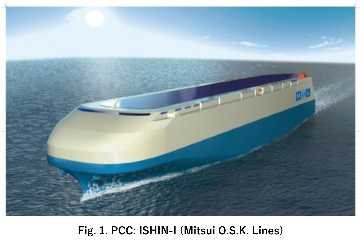
MOL Tech decided to focus on a wind resistance-reducing design for car carriers, which are highly susceptible to wind resistance, particularly because the upper structure has a large area that significantly affects propulsion. In addition, 10 years ago, we announced “ISHIN-I,” as shown in Fig. 1, as a hull design based on the following concept.
Characteristics of Bow and Upper Deck Side Shape
We have already studied ways to reduce wind resistance such as rectifying air flow by aerodynamically rounding the vessel’s bow to help reduce pressure from headwinds. This design has already become a de facto standard in the industry.
However, in the conventional hull design, the shape of the bridge was separated from the upper structure. Therefore, we increased the effect of reducing headwind resistance by embedding the bridge into the hull.
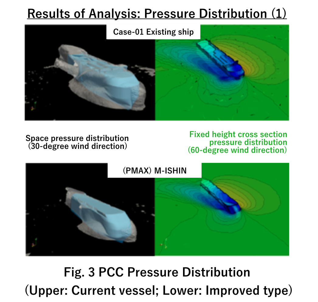
Actually, this does more than reduce wind resistance. In a 60-degree diagonal headwind, it creates thrust of up to twice the force as the headwind resistance. This is an excellent hull design, in which additional thrust occurs in a broad range from 40-degree diagonally headwind to a wind coming from directly behind the vessel. Please refer to Fig. 3 Pressure Distribution.
In addition, the upper deck is both side cut corners along the full side line to create a corner shape effect. This suppresses the separation of air flow at the edges under diagonal winds and cross winds, reducing the adverse effects of cross winds.
This in turn reduces leeway, which notably occurs on car carriers, reduces seawater resistance caused by wind, and helps improve fuel efficiency.
Stern Shape
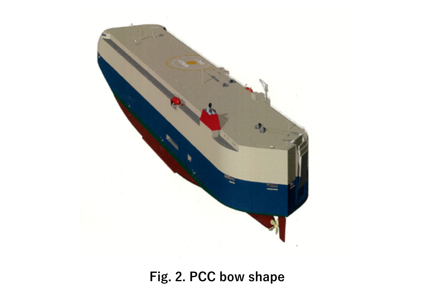
Generally, today’s mainstream in car carrier stern design is a box shape, like a building. This maximizes vehicle loading capacity and allows room to accommodate a rampway required to load and unload vehicles at the stern. On the other hand, the box shape increases wind resistance while underway, causing air to swirl around the stern. As a result, the force of this swirling air pulls in the opposite direction of the ship’s propulsive force, creating a negative effect on performance. Therefore, we developed a hull design that improves propulsion performance by rectifying the swirling air currents that occur at the stern while underway, with a teardrop-shaped stern that integrates the rampway. Please refer to Fig. 2.
As a result, the new design can achieve about a 6% energy savings compared to the current hull design, in a simulation of typical average ocean conditions (wind force) on a north trans-Pacific voyage.
MOL is currently studying the adoption of this hull design.